[A combination of my knowledge of the German language and Google's. Click images to get a bigger size]
Die
Bilder sind nicht in allen Einzelheiten für die Ausführung der
Geräte maßgebend. Für wissen- schaftliche Veröffentlichungen
stellen wir Druckstöcke der Bilder oder Verkleinerungen davon —
soweit sie vorhanden sind — gern zur Verfügung. Die Wiedergabe von
Bildern oder Text ohne unsere Genehmigung ist nicht gestattet. Das
Recht der Übersetzung ist vorbehalten.VEB
CARL ZEISS JENA
Abteilung
für Mikroskopie Drahtwort: Zeisswerk Jena Fernsprecher 3541
COMMENT:
Phase contrast is a standard feature in modern microscopes and "Prof. Zernike, Groningen, received the Nobel Prize in Physics for his
phase contrast method". See the "Afterword" in ths article.
The prize for a modern standard microscope, with the same functionality, is around 1700€
END COMMENT.
Is is the task of
microscopy to make the smallest objects and object structures as
visible as possible to the eye. For objects that differ from their
surroundings in their absorption (so-called amplitude objects), as
Abbe has shown, this is always possible if the aperture of the
objective is large enough to resolve the object structures. This
subheading includes: B. colored histological sections and smears or
scattering preparations of diatoms in air. It is different with such
objects, which differ from the surroundings only by a different
refractive index (so-called phase objects), such as unstained frozen
sections or coverslip preparations from living bacteria or from
infusory bloating.
The latter remain
invisible in the normal bright field image, since their brightness
does not differ from the surroundings. This is where the phase
contrast method specified by the Dutch physicist Zernike 1) in 1932
and theoretically founded by him begins, which in all its points is
based on the consistent application of the Abbe theory of image
formation in a microscope to phase objects and first in the Jena
Zeisswerk by A. Köhler and W Loos has been introduced into
microscopic practice. With the help of this method, the refractive
index in the phase object that deviates from the environment is
converted into a brightness that deviates from the environment in the
image of the phase object. To gain a deeper understanding of the
process, the essence of Abbe's theory must first be explained.
Their physical basis
is Huygens' principle of light propagation and the diffraction of
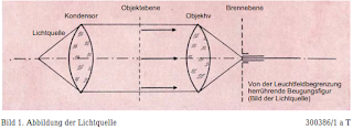
light derived from it. Assuming a point of light in the front
condenser focal plane, the object plane is struck by a parallel light
beam and any inhomogeneity in it caused by that of the surroundings
[1) see epilogue 3E] deviating absorption or refractive index,
creates a Fraunhofer diffraction pattern of the light source in the
rear focal plane of the lens. Since their extension is inversely
related to the size of the object, it is spread apart for a
sufficiently small object, while the diffraction figure created by
the sufficiently large limitation of the illuminated field contracts
with the geometric image of the light source (Figure 1).
This
corresponds to the direct light unaffected by the object. Abbe
describes the entire diffraction phenomenon in the rear focal plane
as the primary intermediate image. The actual intermediate image in
the image plane (according to Abbe: secondary intermediate image) is
then created by superimposing (interference) the light excitation
resulting from the two diffraction figures mentioned above. Abbe has
also experimentally proven that the diffraction phenomenon in the
rear lens focal plane is essential for image formation. He used an
amplitude grating (ordinary line grating) as an object for his
experiments and was able to show that a suitable intervention in the
rear focal plane can give an image that is not object-like. Zernike
has used this knowledge to visualize phase objects. The phase
contrast method is therefore an object-unlike image in the Abbe's
sense. The essence of the process can best be clarified using vector
notation.
A vector is a
directed quantity, i. 2. It is only clearly defined when the amount
and direction are specified. It can be represented by an arrow and
broken down into components; it is identified with a German letter.
Examples from physics are the velocity v and the force K.4
If you idealize the
wave trains emitted by a light source as infinitely extended sine
waves, you can represent them in a known manner with the help of an
arrow rotating at constant speed, which we want to call the light
vector (Figure 2).
Figure
2. Representation of a sine wave 300390/1aT
The state of
vibration can therefore be represented at any point and at any time
by a light vector. The intensity is then given by the square of the
amount
The
parallel light beam originating from a point light source in the
front focal plane of the condenser corresponds to a plane wave and
therefore has the same phase position in the entire object plane;
this can be indicated with arrows of the same direction (Figure 1).
Provided that no specimen is initially placed, only diffraction at
the light beam limit will occur. Since the diameter of the light beam
used is always large compared to the light wavelength, the
diffraction figure has only a very small extent; the light source is
imaged in the rear lens focal plane.
f there
is now a small inhomogeneity in the object plane, the direction and
length of the light vector have changed behind this point in relation
to the homogeneous environment, depending on 5 | r | = ao =
Amplitudeφ = phaser angle a = ao · sin φ = Deflection image 3 300
388 / aT light vectors in the object level
whether it is a place
with a different refractive index or different absorption. Generally
both will be the case. This modified vector r can, as indicated in
Figure 3, becomposed
of a vector ru
, which corresponds to he undisturbed light, and an additional vector
rz,caused
by the interference.

Light
vectors in the object plane Fig. 3 300 388 /aT
This
additional vector thus corresponds to the light diffracted from the
small object. So we now have the image of the light source in the
focal point in the rear lens focal point, caused by the undisturbed
light, and - depending on the size of the
object
- a more or less extensive diffraction figure of the light source,
which is associated with the additional vector, and is derived from
the latter (Photo 4). Since all rays that contribute to the imaging
of the small object have the same optical path length, the vectors ru
and rz
in the image plane are composed in the same way as the corresponding
vectors r and rz
immediately behind the object.
Figure
4. Phase contrast Microscopic image of a phase object 300391/1 a T
The
fact that the eye only perceives amplitude differences but no phase
differences follows from the fact that a pure phase object remains
invisible in the normal microscopic image, because in this case | r |
= | ru | or
| r '| = | r'u
| , If the vector r'u
or r'z could
be rotated so that both were oriented in the same or opposite
directions, a larger or smaller resulting vector would be obtained at
the location of the image, that is greater or smaller amplitude and
thus greater or smaller brightness than in the
surroundings.
This would have made the phase object visible in the image. Zernike
has shown that this is possible by consistently applying the Abbe
theory to non-absorbing objects. Since only small objects are of
interest in microscopy, the diffraction figure they produce always
extends considerably, so that with a sufficiently small light source,
its image can be seen in the rear focal plane covers the diffraction
figure mentioned only slightly and you can largely influence both
separately. In the descriptive explanation, we want to restrict
ourselves to phase objects with very small phase changes. Then the
additional vector stands almost vertically on the undisturbed vector,
so that you only have to attach a plate in the geometric image of the
light source that rotates the phase of the latter by ± 90 ° (Figure
4).
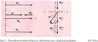
Bild
5. Phasenkontrastmikroskopische Abbildung eines Amplitudenobjektes
300 389/a
Figure 5. Phase contrast microscopic image of an amplitude object 300 389/a
The
positive contrast is shown in the illustration (the phase change
caused by the phase plate
is - 90
°), places with a higher refractive index appear darker than the
surroundings. In the case of small phase changes, the additional
vector is significantly smaller I than the undisturbed vector, so
that the amount of the resulting and undisturbed vector, ie | r '|
and | r'u |,
and thus only slightly differentiate the brightness in the image of
the object from that of the surroundings. For this reason, the phase
plate is given an absorbing effect at the same time and the amount of
the resulting vector can thus be reduced to zero, that is. reach
complete darkness in the image of the object. However, one has to
accept that small amplitude objects disappear in the picture or
appear even brighter than the surroundings; this is evident from the
illustration in Figure 5, which is analogous to that in Figure 4.
Basically,
phase and amplitude objects with maximum contrast cannot be imaged at
the same time. With the previous restriction to small relative phase
changes in the object, a phase change of 90 ° caused by the phase
plate has proven to be the most advantageous, since in this case the
additional vector in
the object stands almost perpendicular to the
undisturbed vector (Figure 4). This no longer applies to larger
relative phase changes in the object. Here, other phase changes in
the phase plate deviating from 90 ° are the cheapest, and its most
favorable permeability then also depends on the object. Strictly
speaking, a phase plate of a specific permeability and phase change
would be required to achieve optimal contrast for each object. This
requirement led to the variable phase contrast proposed by some
authors. A suitable combination of polarizers with a birefringent
crystal plate can be used to continuously change the phase change and
permeability, but in practice this proposal, which is good in itself,
is of little importance for the following reasons:
1. It has been shown that
in 90% to 95% of all cases you can get by with a fixed phase plate of
90 ° phase change with a permeability of 25% for each lens. This
fact can be justified by the fact that in phase contrast imaging only
objects with a very small relative phase change are of interest,
since others usually already absorb so strongly that they can also be
observed quite well in the bright field.
2.The microscope is
extremely sensitive to interference in the beam path (this is
precisely the basis of the phase contrast method). One must therefore
always endeavor to introduce as few additional, optically effective
agents into the beam path and to manufacture them with extreme
precision. With the device mentioned to achieve variable phase
contrast this can hardly be realized, so that an image deterioration
can be expected in any case, especially with strong lenses.
Another complication
arises in practical use. Since the light source and thus also the
phase plate must have a certain extent in order to achieve sufficient
image brightness, part of the diffraction figure originating from the
object is always influenced by the phase plate. This leads to
structures in the image of a phase object that are not present in the
object itself. Bright courtyards are created around the phase object
and brightening inside. So you have to give the aperture diaphragm
and thus also the phase plate such a shape that the disruptive
influence is as small as possible with the largest possible luminous
area. These conditions are best met by the annulus. It is therefore
not surprising that all replicas of our Jena phase contrast device
that have appeared on the market so far use the ring diaphragm and
the ring-shaped phase plate. In addition, it is easy to see from the
explanation given that the disruptive influence becomes smaller and
smaller as the object becomes smaller and the phase ring narrows.
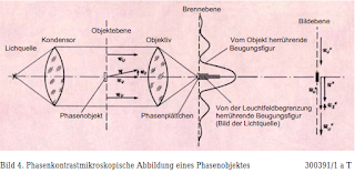
Fig.
6. Köhlersches lighting principle 300 387/1aT
These critical
considerations can in no way reduce the importance of the phase
contrast method; on the contrary, only when you know the effect of
the method can you be largely protected against misdiagnosis based on
the images obtained.
In this context, it should
be particularly pointed out that with less known objects it is
absolutely necessary to compare the bright field image with each
phase contrast image. The many scientific publications of recent
times testify to the success of the phase contrast method.
Image 7 300 385 / a
Annular phase plate in the focal plane of the lens on the image side
The Köhler lighting
principle (Figure 6) is used to carry out the process in practice.
First of all, this achieves the uniform illumination of a sharply
delimited part of the object plane and also the required mapping of
the aperture diaphragm into the rear lens focal plane, in the
following way:
The light source is imaged
with the help of a collector lens in the front condenser focal plane
(aperture diaphragm plane) and together with the aperture diaphragm
by condenser + objective in the rear lens focal plane. The phase
plate arranged here is designed so that it just covers the image
after adjustment of the aperture diaphragm. To limit the illuminated
object field, a light field diaphragm designed as an iris is attached
directly behind the collector lens and imaged in the object plane
with the aid of the condenser.
Bild
10. Ringblendenzentrierung300 384/a
Fig. 10. Ring aperture
centering 300 384/a
To set the Köhler
principle, place a conventional transmitted-light specimen on the
microscope table, focus on the specimen after the lighting has been
roughly set up, and then adjust the height of the condenser until the
light field diaphragm appears sharp at the same time as the specimen.
Then it is opened until the field of view is just illuminated.
n order
not to impair the centering accuracy of the lenses, which is already
increased in Zeiss devices, through arbitrarily operated centering,
the centering option for the ring diaphragm images was placed in the
condenser. With the Zeiss phase condenser, this is done with the
tried and tested three-point centering, with the Lumipan with the
eccentric device of the aperture diaphragm.
Since phase plates (Fig. 7) of
different dimensions are required for the lenses used for phase
contrast observation due to their different apertures, aperture
diaphragms of different dimensions also had to be provided. Two
solutions have been found for this: firstly, the diaphragm turret
(Fig. 8), which carries the various diaphragms in an approximately
aperture diaphragm plane, and secondly, the variable imaging using a
pancratic system under the condenser, as the "Lumipan" (
Fig. 9) was the first microscope to be able to achieve a perfect
phase contrast image by precisely adjusting the ring diaphragm image
(Fig. 10) .For this it is necessary that the ring diaphragm that
matches the lens used is always switched on.
The auxiliary microscope
belonging to each phase contrast device (Figure 11) is used to
observe the centering, with which the ring diaphragm image and the
phase ring in the rear focal plane of the lens can be viewed (Figure
10).
Although the phase plates
we use can be used for the entire visible spectral range, that is,
with the help of our phase contrast device, phase structures can be
made visible in objects of any color, it is advisable to observe a
limited spectral range to emphasize the last subtleties to use. Since
green light is the most pleasant for the eye, each phase contrast
device is given a light filter with the maximum permeability at 550
mμ.
A prerequisite for working
successfully with the phase contrast device is a microscope light
with a collector and iris diaphragm like the types D and E
manufactured by us as well as a microscope with a height-adjustable,
interchangeable condenser like our L-tripods. At the Lumipan research
microscope, the demand for an optically flawless luminaire with the
built-in lighting has been met; the interchangeability of the
condenser is not applicable with regard to the pancratic system.
The following parts
therefore form the Zeiss phase contrast device for normal microscopes
(Figure 13):
1. Phase condenser, a dry condenser not
specified, 0.65, with aperture turret including 4 ring apertures and
2 free passages
2. Phase objectives Achromat Ph 10 / 0.30;
Ph 20 / 0.40; Ph 40 / 0.65; Ph 90 / 1.25 H. I, marked as such by a
red-inlaid Ph
3. Separate microscope for alignment
4.
Yellow-Green filter
The condenser contains an
iris diaphragm, so that when a free passage of the diaphragm turret
is switched on, it can be observed like any dry condenser in the
bright field and is to be used in polarized light and for
luminescence microscopy. The four lenses are correct according to
achromatic lenses and can also be used for ordinary bright field
observation.
In the future, the phase
condenser with individual centering (Fig. 14) will replace the phase
condenser shown in Fig. 13. It has the essential advantage over the
current design that the ring diaphragms can be individually centered
for the respective Ph objective; In addition, the position of the
aperture diaphragm can be easily read from a division.
The phase contrast device
for the "Lumipan" (see Fig. 9) contains a ring diaphragm
instead of the unnecessary phase condenser, which is inserted into
the colored glass holder above the aperture diaphragm. Otherwise, the
two equipment are completely identical.
The hundreds of years of
scientific work that have been carried out with the phase contrast
microscope clearly shows the importance of this method. It is
essentially based on the following points:
![]()
![]()
The phase contrast method
allows the observation of living or surviving material without the
dubious aids previously required for this purpose. Since living
objects often have a refractive index very similar to their
surrounding medium and are usually not very impressively colored, the
bright field observation in this case resulted in extremely
low-contrast images. The attempt was made to increase the contrast by
closing the aperture diaphragm, adjusting the focus beyond the best,
or using vital stains. All of these methods have considerable
disadvantages: closing the aperture diaphragm limits the lighting
aperture and thus significantly reduces the resolution, setting
outside the best focus logically results in blurred images, and vital
coloring represents an ultimately uncontrollable intervention in the
life of the object.
In the dark field
observation that is frequently used, one only sees the outer contours
of a phase object and cannot therefore infer its inner structure
based on the dark field image.
The phase contrast method
enables the living observation of the object in the natural,
surrounding medium. With somewhat careful treatment, the observation
material can be cultivated further and so z. B. Study development
processes in life. Such works are e.g. B. possible with bacterial,
fungal and tissue cultures as well as smears, smears, [‘Klatsch-’
/ test-] and squeeze preparations of various objects.
Hand and frozen sections
of unfixed tissue are also well suited for phase contrast
observation. It is therefore understandable that the phase-contrast
microscopic examinations come mainly from the fields of biology,
medicine and microbiology.
For example, cell division
processes were examined and filmed several times, sperm examinations
were carried out, and mitochrondria and Golgi apparatuses were
observed.
Of particular interest has been the phase
contrast microscopic examination of malignant tumors. Several papers
dealt with the application of the phase contrast microscope in normal
and pathological histology; it was found that the phase contrast
method may show more details within colored complexes than the
brightfield observation, even in colored specimens.
Much
work has also been published on phase contrast observations on living
bacteria, and more recently the phase contrast microscopic
examination of fresh blood has proven to be promising.
In entomology, the phase
contrast method has been used to observe and systematically determine
the smallest objects such as mites, mallophages and the like. a.,
proven. In these transparent objects, the phase contrast microscope
shows the finest hair and bristles as well as systematically
important chitin structures more clearly than any other
device.
Paleontology uses the phase contrast microscope
e.g. B. for pollen analysis, and in the study of the structure of
coal, its application has led to new results as well as in fiber and
textile research.
he
phase contrast method has also been used to examine surfaces, in
particular by examining the polishing of optical surfaces on glasses,
taking collodion or lacquer prints from opaque objects and observing
them in transmitted light. The phase contrast method has also been
used in the field of mineralogical as well as ore and metal
microscopy, where investigations are carried out on thin sections and
with the help of varnish prints.
This short, by no means
exhaustive summary of the possible uses of the phase contrast
microscope shows that over the course of 13 years this device has
become an indispensable tool in microscopy. A compilation of
publications in the field of phase contrast microscopy that have
become known to us is given in our publication CZ 30-L304a-l
"Directory of documents on phase contrast microscopy".
Afterword
In November 1953,
Prof. Zernike, Groningen, received the Nobel Prize in Physics for his
phase contrast method. Since then, various notes on this topic have
been published, which do not always correctly depict the facts in
their historical development. Therefore, it seems appropriate to us,
based on the documents available to us, to reproduce the development
of the method and the devices necessary for its implementation true
to history. The theoretical foundations of the phase contrast method
were already communicated to us by Prof. Zernike in 1932 and 1933 or
in Jena from Inventor demonstrated by means of several experiments on
suitable objects. In 1933 and 1934, Prof. Zernike published
fundamental works on it in various magazines. (Handelingen van het
XXIVe Ned. Natuur- u. Geneskundig Congr. 18 to 20 April te
Wagenlingen [1933]; Physica 1934; Z. f. Physik 1934 etc.) The patent
for this process (DRP 636 Kl. 24 H Gr 610) was issued to Carl Zeiss,
Jena, in May 1935. There was a relatively long time between this
point in time and the practical implementation of the process on a
microscope or until a salable device was sold in 1941. However, it
meant years of hard work for the scientific staff at Carl Zeiss,
Jena, who were involved at the time, during which some setbacks had
to be overcome. We consider ourselves entitled to, in this context,
especially the name of our now deceased employee, Prof. Dr. Dr. H. c.
August Köhler, who pioneered this area and shared his experience and
practical results in 1941 with Dr. Loos published in the journal "Die
Naturwissenschaften". It is now generally known that the phase
contrast device for microscopy is now produced again in the known
quality, and in an improved form, in the VEB Carl Zeiss Jena. Of
course, we are also at the birthplace of the practical Realization of
the phase contrast process for its further development is constantly
striving.
January 15, 1954
Translation from German: Google Translate with some
help from
per.funke@gmail.com
The translation method has it’s
pitfalls. The original originates from
Errors, ambiguities etc. may be
resolved by correlating with this document, the "original".
If the link ends up in the big 404-bucket I can supply the PDF.
Just for sake of interest, look through
the"Afterword".